How to build a Hebel PowerFloor deck

Hebel PowerFloor is a highly versatile, 75mm thick, solid flooring system that gives you the feel of a concrete floor at a significantly lower cost and much easier installation.

Simply installed over conventional floor framing such as decking joists, the system of panels fit snugly together to form a solid, strong, smooth floor. It is the perfect base for ceramic tiles.

PowerFloor’s superior termite-resistance, low noise transmission, thermal insulation properties and fire resistance make it the perfect choice for your deck.

Step-by-step guide:

Ensure you have decided on the right sub floor design requirements for decking bearers and joists to get the best result.

Fig. 1.1

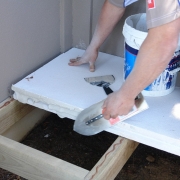
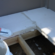
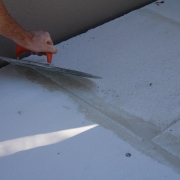
Hebel PowerFloor is a standard platform flooring system, and is well suited to be fixed over both timber and steel decking systems. It’s recommended that professional services be sought to ensure the proper and safe design of all flooring support structures.

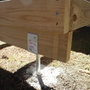
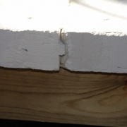
Minimum joist bearing width for PowerFloor is 45mm.

Although PowerFloor is suited to similar deflection limits as timber and fibre cement flooring systems, the more limited deflection, the closer PowerFloor will feel to a full suspended concrete slab.

Hebel recommends a deflection limit of span/600 to achieve the ultimate feel and superior performance of PowerFloor, particularly if larger size ceramic tiles are to be laid on the floor.

Ensure you have considered the right sub floor design for PowerFloor load limits.

Fig. 2.1

Hebel PowerFloor systems can support a maximum uniformly distributed load of 5kPa, or concentrated (point) load of 1.8kN over a load area of 350mm2 (with joists at 450mm or 600mm centres only) 3.9kN over a load area of 10,000mm2. For loads outside this range, please contact CSR Hebel.

The following minimum deflection limits in the design of all bearers and joists is recommended: Dead Load (DL): span/300 or 12.5mm max, Live Load (LL): span/360 or 9mm max. Dynamic Response: 2mm max. under a 1kN point load. Hebel PowerFloor has a self weight on the sub-floor structure of 52kg/m2.

There will also be a further dead load on the structure depending on the type and thickness of tiles laid over the PowerFloor, and this should be accommodated in the structural design.

Preparation of the framing for Hebel PowerFloor Panel installation.

Fig. 3.1

Ensure the sub-floor deck structure is installed to the designer/manufacturers specifications.

Check decking floor framing is complete and within level tolerances of max a 5mm per 6 metres of deck length.

Draw set-out chalk lines across joists at 600mm width, this will ensure panels are easily laid straight and true across joist spacings.

Run a string line along these chalk lines to cross check the level of the sub-floor structure.

Ensure any high or low spots are rectified prior to commencing installation of the panels. Ensure a min. bearing area of 100mm x 100mm for any load onto the PowerFloor (eg a pergola post base) and the bearing stress does not exceed 1mPa.

Any concentrated load must be either blocked between joists or supported with further joists as required.

First calculate the total floor area of the deck in m2 and generally allow an additional 3% waste from cutting panels to create a staggerbond panel layout.

If possible, design the deck area in multiples of 600mm for the most efficient coverage of PowerFloor panels.

Decks that are complex in shape may incur higher waste and a detailed layout should be drawn on a plan prior to installation.

Use the following ratios to calculate general material requirements:

  • each PowerFloor sheet is 1800 x 600mm and covers an area of 1.08m2 (Use 1sheet/1m2 for basic planning)
  • number Screws @ 450mm joist centres = 8 screws/m2 area of floor
  • number Screws@ 600mm joist centres = 6 screws/m2 area of floor
  • Hebel Adhesive = One 20kg bag per 20m2 area of floor
  • construction adhesive - each tube of construction adhesive glues approx. 10 panels to the sub floor joists.

Complete a detailed panel layout drawn on paper starting at the most open corner of the deck and working across the deck perpendicular to the joists/bearers.

The panels are laid in a stagger bond pattern so some panels will need to be cut to create the starting panel on alternate rows of flooring – this starting panel must be a minimum of 450mm in length and rest solidly on a joist at each end of the starter panel.

NOTE: Panel storage

Full packs of PowerFloor should be placed on even level ground at convenient locations surrounding the work area. PowerFloor panels are packed vertically for transport. As soon as a pack is opened the sheets should be laid flat and horizontal on level gluts to ensure loose panels can’t topple over.

If stored on the deck working area, ensure that panel bundles/packs are stored in an allocated area of the floor designed by the structural engineer that can support the weight of the panel stacks.

Fig. 6.1

Cutting PowerFloor panels are cut using a circular blade power saw fitted with a diamond encrusted, continuous rim, ‘turbo’ sided masonry blade and vacuum extraction system.

A straight edge cutting fence or square should be used to ensure straight cross-cuts that are perpendicular to the panel length. Set the blade to cut @ 72mm depth and cut all panels horizontally with full support underneath – there is no need to cut totally through the panel – the last couple of mm thickness will simply and easily break.

Cutting will expose the internal steel reinforcement inside the panel. This exposed steel must be re-coated by simply painting on a layer of Hebel anti-corrosion paint.

Fig. 7.1
Fig. 7.2
Fig. 7.3
Fig. 7.4
Fig. 7.5

Position Hebel PowerFloor sheets loosely and flat on the sub-floor framing ready to install.

Provide a temporary installation platform using PowerFloor sheets or other suitable formwork type panels over joists where necessary to ensure a safe working area and proper footing.

No flooring product should ever be installed by standing on open narrow joists or leaning over open spaces.

Panels are to be installed in a stretcher (or stagger) bond pattern, Use lifting handles or trolley to move the panels to the installation area and into final position.

NOTE: Safety Tip - Hebel PowerFloor is made from natural sand, cement and minerals. Like all building products where masonry dust is generated in fabrication, proper respiratory, eye and hearing protection must be worn.

Adhesive

Apply a 5mm min. bead of Fuller Max Bond construction adhesive (or equivalent) to top of joists in accordance with manufacturer’s instructions, and apply Hebel Adhesive, with a trowel, to all appropriate Hebel PowerFloor panel edges. Apply just before laying panel to ensure adhesive does not skin over.

Panels must be installed with minimal horizontal sliding onto the joists to ensure a good bond of the construction adhesive.

Force the Hebel tongue and groove joint closed as the panel is rolled and lowered onto the joists. Ensure all joints are tight and that adhesive makes full contact along all joints.

A small amount of ‘squeeze out’ of Hebel adhesive should be observed on sides of panel joint.

Fig. 7.6
Fig. 7.7

Fixing

Screw fix all panel to the joists as required. Panels are screwed down directly on all joists along the panel length. All panel ends must rest directly on at least 50% of the joist width.

Given the more narrow bearing at panel ends, fixings can be skew angle fixed into the joist underneath however, all panel ends can be simply glued down to the joist with construction adhesive and then fully butt-joint glued ‘panel end to panel end’ with a full squeeze out of Hebel adhesive.

Repeat this process across the entire floor area, removing excess Hebel adhesive as construction takes place.

All Powerfloor panel ends and long edges must be screw fixed around the entire perimeter of the deck.

Control Joints

Control joints are a necessary part of Hebel PowerFloor systems.

Control joints provide a region in which to relieve stress due to normal movement of the structure, and to control the location where movement can occur without a detrimental effect on the floor finish.

Control joints should be a minimum width of 8mm, packed with a closed cell backing rod and calked with an exterior grade flexible caulking sealant.

Recommended locations for control joints are:

  • Typically at a max. floor area spacing of 6000mm.
  • Over lines of support for the joists
  • Located at changes in joist orientation.
Fig. 8.1

Hebel Powerfloor can be drilled for service penetrations (water, power, gas, plumbing etc) up to 80mm in diameter without structural effect, with a minimum distance of 450mm between such penetrations.

Multiple penetrations in a small area should be fully supported by blocking. Blocking must be installed to support Hebel PowerFloor panels at any major openings. (e.g.,) rebate for a recessed landing or stair case).

Scrape all excess Hebel adhesive while still wet, preferably just after the glue has begun to stiffen as this will make it easier.

After the adhesive has dried sweep the floor surface to remove debris and loose particles. Fill any joint gaps and screw holes with Hebel Adhesive, as required.

Clean and expose any surface blemishes such as chips, cracks, gaps, ridges or the like.

Fill all unacceptable locations with an appropriate and compatible patching compound such as Hebel Patch as required. Ensure panels are then allowed to dry.

PowerFloor can be sanded if required to achieve a very smooth clean finish (ensure dust extraction and or respiratory protection when sanding PowerFloor).

Prior to ceramic tile installation the entire PowerFloor area should be sealed with a roll-on waterproofing membrane solution. This will ensure a proper key for the subsequent tile adhesive, and ensure that if at any time the tile surface or grout allows water penetration, the membrane will impede moisture penetration into the PowerFloor deck floor.

Install tiles per manufacturer’s guidelines, using an exterior grade tile adhesive that is compatible with the waterproofing membrane.

Apply the tile adhesive as per the manufacturer’s instruction.

All exterior decks should have a slight fall to ensure any rain or water on the deck will drain effectively away to the outside perimeter – this is imperative for open decks.

Notes:

Control Joints - ensure Control Joints are installed in tiles at the appropriate location above PowerFloor Control Joints.

Penetrations - seal all penetrations through waterproof membrane.

Materials required:

Shopping List


Tools Required

What components you'll need

  • Fasteners
  • The correct sized fasteners for PowerFloor must always be used. Screws for fixing Hebel PowerFloor panels to Timber Joists: 14-10 x 100mm MP Bugle Head Batten Screws or equivalent. Screws for fixing Hebel PowerFloor panels to Steel Joists: 14-10 x 95mm Hex Head Self-tapping Screws or equivalent (no seal required). This fastener is suitable for metal thickness <3mm. Refer to screw manufacturer’s guidelines.

  • Timber & Steel
  • Support Systems Timber or steel floor framing can be used to support the Hebel PowerFloor panels. The allowable spacing of the joists is 450mm or 600mm only. Either spacings are suitable for 75mm PowerFloor Panels. The joists, bearers and other supports shall be sized in accordance with the framing manufacturer’s recommendations or by a qualified structural engineer. Where steel joist framing is used it must be ensured that the PowerFloor panels are provided with uniform and complete bearing onto each steel joist.

    Note: The designer should allow at least 51kg/m2 for the self weight of the Hebel PowerFloor panel. A minimum joist flange width of 45mm is required.

  • Hebel Adhesive
  • Hebel Adhesive (supplied in 20kg bags) is used for gluing the panels together at all joints. Typically, panel joints are 2-3mm thick. Sufficient pressure should be applied to the joint to ensure full coverage of adhesive in the joint. Adhesive is to be mixed to the proportions as stated on the bag.

  • Construction Adhesive
  • A 5mm (minimum) bead of Fuller Max Bond construction adhesive is applied to the top of the joists. Ensure the surface is free of coatings and loose material that may inhibit bond.

  • Caulking
  • All gaps at openings, penetrations and control joints should be completely sealed with an appropriate flexible exterior sealant, installed over an expanding foam backing rod and applied in accordance with the sealant manufacturer’s specifications.

  • Hebel Patch
  • Minor chips or damage to PowerFloor panels are to be repaired using Hebel Patch. Hebel Patch is available in 10kg bags.

  • Hebel Anti-Corrosion protection paint
  • Any reinforcement that is exposed when panels are cut must be coated with a liberal application of Hebel anti-corrosion protection paint.


Safety information

As with all cementitious products, the user should take all precautions associated with cutting concrete. These precautions include: P1 or P2 class respirators (for fine dust from powered cutting tools), eye protection and ear protection, as well as long sleeved clothes and gloves, as dust could irritate the skin. Hebel recommends reading all relevant Material Safety Data Sheets (MSDS) prior to working with Hebel products.

Find a Supplier

To find a supplier click through to the Contact Us and Select your Specialist Reseller or Hardware store.

Contact Us

Subscribe to Hebel Matters.

To stay up to date with the latest Hebel news, articles and feature projects, enter your email to sign up to our monthly e-newsletter.

Subscribe

    Thank you for submitting the form.

    CSR

    Privacy Policy | © 2024 Copyright Hebel.

    Top